microwave cable TV (MDS/MMDS) antenna conversion to 802.11b (2.4GHz)
This document is a work in process, and may have incorrect information.  Add salt as necessary.
freshness date: 20041001

The goal of this project is to modify old antennas for point to point 802.11 links, which is a key component in another project of mine.  (link to come later)

I you just happen to have an extra MMDS antenna, this is a project to convert that antenna into a high gain, directional 802.11b antenna for point to point link.  In the town I live in, the company that was providing cable TV service on the MDS band has gone bankrupt, and abandoned the antennas on the customers' houses.

The wireless microwave cable band is 2.500 - 2.686 GHz, and (without digital encoding) carries 31 TV channels.  There're 2 more channels that these systems carry on another 12MHz chunk of bandwidth between the primary chunk of bandwidth and 2.15 GHz. 

The 802.11b (and 802.11g) standard utilizes bandwidth in the ISM band of 2.4000 - 2.4835 GHz.  (802.11a uses frequencies 5.150 - 5.825 GHz, and is not compatible with this project.)  Because of how close the ISM band is to the band used by the existing antenna, this project is theorizing that converting these antennas will be a reasonable project for a hobbyist.

I started off with an antenna left over from the MMDS cable system in my town.  The receiver module I have is a California Amplifier model 2030/020. A spec on the reflector I have is here.  The reflector is already rated for the frequencies of interest.
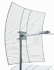
similar antenna, actual model used varied
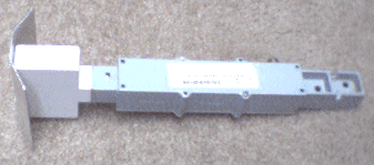
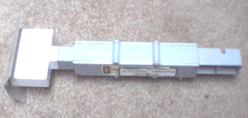
The first thing to do was to remove the antenna element and active electronics module.  Removing a single bolt near the center of the shaft on the antenna allowed this module to be slid out.  The actual antenna is in the white plastic box in the left hand side, and the electronics are in the box in the center.  The bent sheet of aluminum on the far left is a reflector.


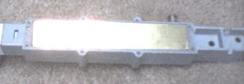
After unscrewing the panels on the box, you'll find a brass colored sheet pressed into the box.  This metal is for shielding.  Taking a small screw driver, the panels can be pried out by lifting from a corner.  Though, one of the two panels is pressed in in such a way, that it didn't want to come out.  I badly bent on of the two panels while removing it.
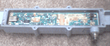
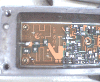
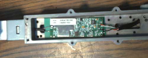
After removing the brass plates, the electronics of the unit were revealed.


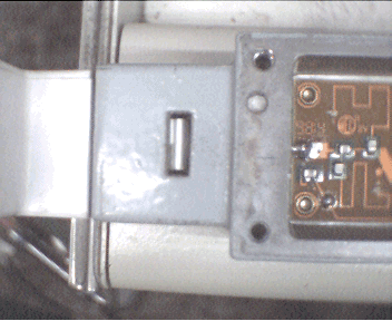
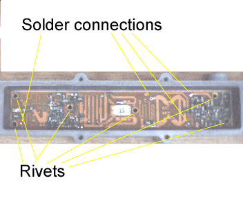
Before the boards can be removed, there are two solder connections that need to be removed.  The connections can be seen as a thick wire coming from the antenna module, and then on the cable connection at the other side of the unit.  In removing the cable connector, I ended up destroying it because of how tight it was in there.  Go the easy route an find a socket that properly fits it.  A crescent wrench may destroy it.  Though, it being a connector for 75 ohm cable, that's not much of a problem because we're converting this thing for use with a USB cable.
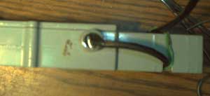
On the antenna side, once you get it unsoldered, you can remove the antenna module.  The module is held in partly by the fingers/hooks shown in this picture (there's one on each side), and partly by a pressure fitting between the cast metal case and the plastic module, as you'll see once you get it apart.  Use a screw driver to press in on the fingers/hooks.  Rock the module back and forth to work the pressure fit part free.


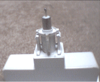
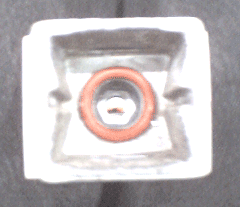
After you get the antenna module removed, this is what that ends look like.
To remove the circuit boards, there're a few rivets to drill through and/or punch out, and a couple electrical connections to unsolder.  The electrical wires that connect the boards are little nails with a head on one side, so they will only come out from one side.  (I forgot which side!)  Start by removing the rivets on the side shown.  Then, gently pry up the board as you heat the solder connections.  If the board doesn't easily lift up, try heating the connection on the other side.


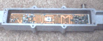
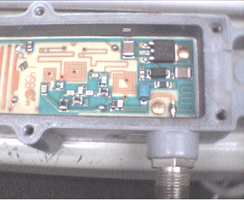
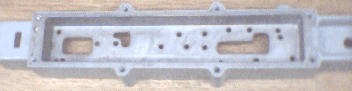
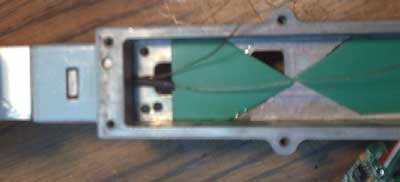
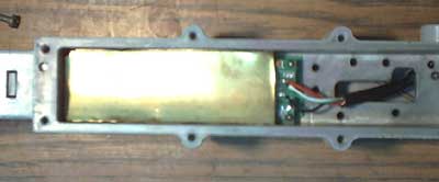
After the boards are removed, this is what's inside the box.
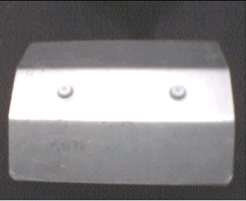
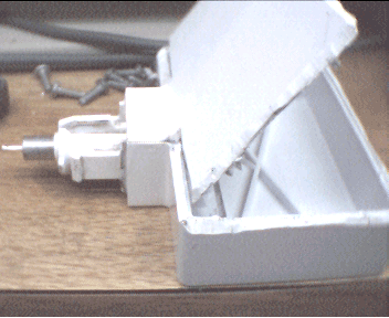
Onto the next major part, the antenna module.  The metal reflector is bonded to the plastic box by a pair of melted posts passed through the plate.  I removed it by cutting away the plastic posts shown, figuring I'd reconnect the plate by glue when I got to that point.


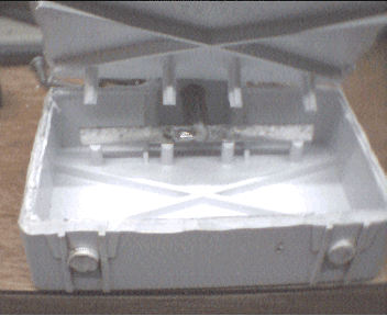
My opening of the box was not nearly as pretty.  There's a seam on the box that can be seen on one edge.  It was glued together with a very strong glue on this edge.  I whittled and shaved away that edge until I cut through the glue, and then bent the plastic open.  Next time around, I may change how I opened it.
With the box open, the antenna element can be seen.  The empty space in the box is to hold the metal plate reflector at a specific distance from the antenna.


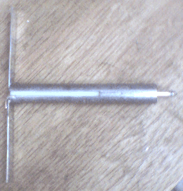
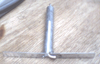
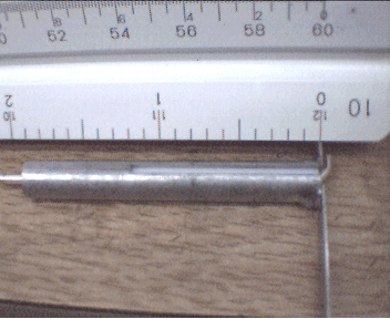
This is the antenna element.  It's a half-wave dipole.


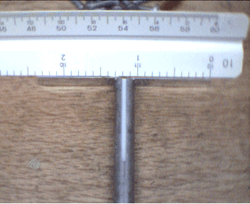
I've surmised that this antenna is a half wave dipole because of it's length and presumed operating frequency.  It has a length of 2.3" (58.42e-3 m), which just happens to be half a wavelength for 2.568 GHz, which is about in the middle of the original band.  Converting it to a half wavelength of the target band will consist of merely adding a fraction of an inch to it's length.  Specifically, it needs to be 2.41" long for 2.45 GHz.
There's a cut down the side of the antenna.  Whether or not the length of this cut needs to be changed, I don't yet know.  My guess is that cut makes this section of the antenna into a transformer that converts the unbalanced signal at the left hand side to a balanced signal at the dipole on the right.  (Or in reverse order, if you're looking at this thing as a receiver.)

More on dipole antenna design:
http://www.packetradio.com/ant.htm is of interest.  Of particular interest is that the impedance of a dipole at its drive point is about 72 ohms.  If the same holds true for this antenna, then the slit in the tube (shown above) is likely part of an impedance transformer.


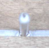
Looking at the unbalanced end of this antenna (cheap webcams don't focus easily), it's essentially a coaxial transmission line.  The size of the inner conductor is 62 mils (1.575e-3 m), and the inner diameter of the outside shell is 180 mils (4.572e-3).

Looking at this page, I found the formula Z0 = 138 / sqrt(epsilon) * log10 (outer_dia / inner_dia).

Assuming that the plastic in the antenna piece is either polyethelene or polypropylene, the calculation I made was for about 42 ohms.  This antenna probably was designed to be 50 ohm at the input.

'Epsilon' is the dielectric constant of the plastic in the transmission line:
TFE 2.03
Polyethylene 2.3
Nylon 4.6-4.0
Polypropylene 2.25

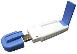
This Linksys WUSB12 or NetGear MA111 look interesting, in that they could be fit inside the metal box and directly connected to the antenna element.  The key questions are: 1) can a USB cable reliable be run as far as would be necessary (or a USB repeater put in), and 2) can it be driven from Linux.

The Linksys WUSB12 specs says it transmits at 14dBm (25mW), and receives signals down to -83dBm.  If an antenna gain of 20dB is achieved on each side, then (being extremely generous), there's about 137dB of loss to allow for the path.

Using the equation Loss = -20 log (4*pi*distance/wave_length), there's ideally 69km (42.8 miles) of distance capability.  I really doubt it'll reach anywhere near this far, because one of Murphey's corollaries says that things in practice will never be as good as they are in paper.  (As often demonstrated by Mr. Wiley Coyote.)  But the numbers suggest that a few miles reach is reasonable.  I expect the biggest distance factor will be interference from other 2.4GHz devices.

Per a report from a member in my local LUG (Linux User's Group), these devices are usuable with Linux!  The trick had to do with taking the generic driver for the chipset that's inside these devices, and then adding the manufacture and device ID numbers to the proper files to get the OS to associate the driver with them.  Hopefully I can convince the guy to write a little instruction page for that, or find one online to link to.


The first real test I plan is to test the performance of this antenna at 802.11b frequencies without modifying the dipole element.

A good free online book about microwave antennas at http://www.qsl.net/n1bwt/contents.htm.

more cool link(s):
Some notes about FCC power regulations in this band:

From the FCC regulation shown, the maximum allowed transmitter power is 30dBm (1 watt), and that's into a 6dBi antenna.  Therefor the maximum EIRP (efective isotropic radiated peak) is 36dBm (4 watts).

But!  In the paragraph I have underlined, you can effectively get a 2dB increase in allowed EIRP for every 3dB increase in antenna directivity.

For illustration using the parts I propose above, let's assume the antenna has a gain of 24dBi, and the transmitter has a power output of +14dBm (25mW).
  • for every 3dB of antenna gain over 6dBi: antenna is 24dBi, minus 6dBi, therefor it's 18dBi over, divide by 3, thus 6dB
  • you reduce the allowed transmitter power by 6dB: the allowed TX power is 30dBm, and is reduced to 24dBm
  • this transmitter is only capable of 14dBm, so no reduction is necessary
  • the full system has an EIRP of 14dBm plus 24dBi, which is 38dBm (6.3 W)
Actually, for the case of a 14dBm transmitter, its power does not have to be reduced until the antenna gain exceeds 54dBi.  With an antenna gain that high, the EIRP would be 6310 Watts at the listed transmitter power.  If you could build an antenna with a gain of 80dBi, your EIRP could be 341 kW.
FCC ISM rules

...(b) The maximum peak output power of the intentional radiator shall not exceed the following:

(1) For frequency hopping systems in the 2400-2483.5 MHz band employing at least 75 hopping channels, all frequency hopping systems in the 5725-5850 MHz band, and all direct sequence systems: 1 watt. For all other frequency hopping systems in the 2400-2483.5 MHz band: 0.125 watts.  ...

...(3) Except as shown in paragraphs (b)(3) (i), (ii) and (iii) of this section, if transmitting antennas of directional gain greater than 6 dBi are used the peak output power from the intentional radiator shall be reduced below the stated values in paragraphs (b)(1) or (b)(2) of this section, as appropriate, by the amount in dB that the directional gain of the antenna exceeds 6 dBi.
       (i) Systems operating in the 2400-2483.5 MHz band that are used exclusively for fixed, point-to-point operations may employ transmitting antennas with directional gain greater than 6 dBi provided the maximum peak output power of the intentional radiator is reduced by 1 dB for every 3 dB that the directional gain of the antenna exceeds 6 dBi. ...
I was given a Gigafast brand 802.11b/USB (model WF-741UIC) adaptor by a friend, and was able to progress to the next step.

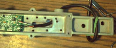
There was a USB connector on the right hand side of the board shown that I desoldered and replaced with a USB cable.  The cable was pulled through the hole in the side of the metal housing before soldered to the board.  The hole needs to be drilled out first.

On this particular board, the antenna was a surface mount component about 3/8" long.  I removed that piece, soldered the antenna "hot" to its pad next to the shielded area, and soldered the antenna ground to the shield.


Before I put the board in, I glued some piece of plactic down underneath it to insulate it.  The wire strands are connected to the antenna.  The wires are bare strands taken from a piece of 12 gauge stranded wire.  The "hot" wire is soldered to the tip of the conductor coming out of the antenna, and has a piece of heatshrink around it to insulate it from the case.  The ground wire is pinched in between the ground of the antenna and the chasis.  I placed the wire in the hole before I put the antenna back in the metal piece.
The board is retained by a piece of the metal I removed from the antenna near the beginning of the project.  There's a piece of plastic glued to the botton of this metal for insulation, and I cut the metal so that the USB connection was not covered.


Here are a couple more pictures of interim steps descibed above but not shown.  Not shown is the antenna after I screwed the sides back on to it.

So far I've tested the antenna by walking down the street and pointing it at the window where an 802.11b access point was.  Looking at the signal meter on the laptop it was connected to, it showed to have directionality because the signal would significantly drop off if I pointed it away from the window.  I wasn't able to test it to much of a distance because I would lose the connection whenever the view to the window was obscurred by another house.

An unmodified PCMCIA 802.11b card was able to hold a link without visual contact to the access point.  I think that is because it had an onmi-antenna and was getting a signal from reflections off houses and fences, whereas the directional antenna did not have power going in directions where it could get a good reflected signal.


still more to come, as I have time

You're welcome to email me if you know any of the answers to the technical questions I've posed here, or if you know of and specific technical errors I have on this page.
picture of email address