









This is a conversion (to HTML) of a method I developed in 1994 for a project I was doing.
Theile and Small have calculated boxes using the same premise as I have used here and with similar technique. There was something about their method that I just wasn't able to grasp, so I have attempted to simplify the method and explain it so one can grasp an intuitive feel. The level of complexity in the box you simulate is dependent on how much detail you decide to put in your model.
This method is not particularly suited to model the efficiency and characteristics of wave propagation since the model will not vary coupling efficiency at different frequencies.
The software used for the refinement of this technique was the shareware version of PSpice v5.3 for DOS. Since even the most complex subwoofer cabinets are still pretty small after converted, this version should be sufficient for most projects. You can find the free student version of their newest software here.
Basic Variables of the Speaker
These are the terms and variables standard to the speaker driver world. I have mostly kept to this convention though out this paper.
Electrical Equivalents: Acoustics to Electricity
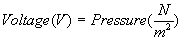


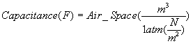
These are the basic equivalents between the electrical domain and the audio spice domain. From these equivalents, the rest of the items in the audio domain are constructed.
When defining the charge/air volume equivalence, it is necessary to specify that the air volume is at one atmosphere in pressure. This is because the equivalence is actually between number of electrons and number of molecules of air. Since the number of air molecules in a cubic meter varies with pressure, it is necessary to specify the volumes at constant pressure.
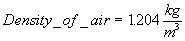
Other constants that are necessary for the conversions are:

Defining a Box or Chamber
Defining the box is the most simple part of the conversion. An ideal box is modeled by a capacitor. The magnitude of the capacitance is the box volume in cubic meters divided by the constant of atmospheric pressure. One terminal of the capacitor is connected to the audio ground reference, and the other is the box. To model the box more realistically, a resistor can be placed in parallel with the capacitor to model air leakage. This is not an easy value to precisely calculate, and should be set similar to values measured from previous boxes constructed with the same carpentry technique.

Defining Ports with a Length
A simple port is modeled with an inductor and a resistor in series. The ends of the port are the ends of the device. The mass of the air in the port and the energy stored when that mass moves is modeled by the inductor and the resistance to air flow is modeled by the resistor. If multiple ports are used in parallel in the cabinet, then the model can be made by just putting the equivalent electrical devices in parallel. If the ports in parallel are of the exact same dimension, then the two elements of each device may be put in series-parallel. This allow the resistances and inductances to be combined in a parallel fashion, reducing the component count and simplifying the calculation.


A side effect of modeling the port as a transmission line is that it models the compressibility of the air in the port. As the volume of the port is increase to be similar to the volume of the box, the basic equations for port and box resonance cannot be used. Due to the fact that most ports are significantly smaller (in volume) than the box they vent, this is not a problem in most in instances.
Modeling the resistance in the port as it actually is, is impractical with these methods. In the audio-spice world, a resistor would model an volume air flow rate that is proportional to the differential of the pressure across the orifice. In the real world of fluid flow, the volume flow rate is proportional to the square root of the pressure differential, and this is assuming either a constant laminar or turbulent flow.
Basic port air flow should be laminar. If the flow is turbulent, than the cross sectional area of the port is too small for the volume velocity it is attempting to pass. Also, as the flow becomes more turbulent, the velocity of the air in the port increases to the point in which it may go supersonic. This is a region of operation in which the box should not be operated.
To be sure that you do not operate in a region where the flow velocity of your port (or vent) is too high, first model the speaker system. Drive the speaker with the maximum voltage you would rate the cabinet at, and then measure the current (volume velocity) through the inductor of the port. Divide this volume velocity by the area of the port. The result will be the velocity of the air in the port in meters per second. Dividing that result by the speed of sound, 330 m/sec, will tell you the MACH of the air in the port. (The speed proportional to the speed of sound.)

{At this time, I have not developed equations for the resistance of the port.}
Defining Vents (Ports without Length)
A vent (slot, round, or otherwise) is modeled as a port with no length. Since the inductance of the port goes to zero when the length of the port goes to zero, a vent is modeled by the resistive portion of the port. Use the equation for port resistance (in the previous section) to model a vent.
Defining a Speaker (open back)
There are two speaker models that can be used in the cabinet modeling. The simple model consists of just the components that model the acoustical and mechanical parts. The complex model combines the simple model with the components detailing the motor assembly of the speaker. With the complex model, the input can be treated like the actual terminals on a speaker. This allows for simulating house a box affects the impedance or complex resistance of a driver or drivers.
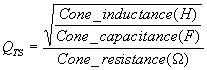
In the simple model, a resistor, capacitor, inductor, and voltage source are put in series. The voltage source simulates the force from the motor (coil) assembly. The capacitor, the stiffness of the suspension. The inductance, the mass of the cone (and air near it) moving. And the resistance, the loss of energy from the motion of the cone. The resistance, in the simple model, also simulates the electrical damping. For this reason, the resistance in this model is high as compared to the complex model. Also, the voltage source cannot be treated as an actual motor assembly.



These equations can be used in both the simple and complex models. Some values are easier to obtain by calculating backwards from known values. With modeling the speaker, this is certainly true for a few of the values. In the simple model, the speaker resistance and inductance can be calculated from specifications provided with most drivers. A simple resonant frequency equation can be modified for this purpose.

 (resonant
frequency) and
(resonant
frequency) and  (equivalent air volume of suspension) of the specific driver. The
equation is reworked to be:
(equivalent air volume of suspension) of the specific driver. The
equation is reworked to be:

 (Q total of the speaker).
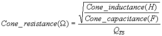
In the complex model, the voltage source is replaced by a current dependent voltage source and current monitor (constant voltage source set to zero) in series and a separate circuit modeling the coil. The coil is modeled by a resistor, dependent voltage source, and current monitor in series. Each dependent source is controlled by the current monitor on the opposite side of the domain.
The coefficient of the acoustical side dependent voltage source is determined by the pressure generated per unit current in the coil. This is a value that is most easily determined by calculating from the BI factor (newtons per amp) of the coil.
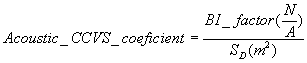

The value of the resistor on the in the electrical domain is simply
the DC resistance of the coil. This is usually specified by the
value  on the spec
sheet. The resistance of the acoustic domain resistor is calculated
similarly to how it was calculated in the simple model. But instead of
using
on the spec
sheet. The resistance of the acoustic domain resistor is calculated
similarly to how it was calculated in the simple model. But instead of
using  in the
calculation, use the value of
in the
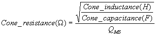
calculation, use the value of  . This is the Q of the speaker from only the mechanical
damping.
. This is the Q of the speaker from only the mechanical
damping.
The coefficient to the dependent voltage source in the electrical
domain reflects the voltage created by the motion of the cone. This is
not a simple value to calculate. Since current in the acoustical domain
relates to air flow, it first has to be converted to velocity of the
cone by dividing the air flow by the area of the cone. After you find
the velocity of the cone per unit or air flow rate, you must then
calculate the voltage induced on the coil by the rate of change in the
flux through the coil. Instead of doing all these calculations, it’s
easier to determine this coefficient by calculating it from the  and all other values in the
model.
and all other values in the
model.
{I have not yet derived the equation for this}
It is important to observe the polarities of the two voltage sources in reference to each other. If they are backwards, then the model will act very strangely.
If the suspension of the speaker is not air-tight, and you wish to include this in the model, then place a resistor in parallel with the complete series chain of the acoustic model of the speaker. There is no easy calculating for this, and usually must be found empirically.
With the complex model, you can drive it with a model of your amplifier and find the effects on the sound produced from the interrelation of the complex resistance of the cabinet and the real world limitations of a non-ideal amp. If you only wish to find the complex resistance of the cabinet, then drive the speaker with a one volt constant AC voltage source. Set up the simulation to run an AC frequency sweep over the range the cabinet will be operated in. From the output file, plot the current into the speaker and the phase of that current. This will allow you to easily calculate the complex resistance.
Since the modeled speaker will move as far as you force it to, it’s
necessary to determine the actual excursion of the speaker if you wish
to calculate the maximum output of the cabinet. The voltage across the
capacitor of the  is
the value to look at. Since the voltage across that capacitor is
directly proportional to the "air" charge in it and the charge is
directly proportional the displacement, this is an easy calculation.
It’s easiest to take the value of the maximum displacement and
calculate
the maximum voltage you may read across that capacitor. Do this by
multiplying the maximum displacement (in one direction) by the area of
the cone to find the maximum volume displacement. Take the volume
displaced and divide it by the capacitance to find the maximum allowable voltage on this
capacitor.
is
the value to look at. Since the voltage across that capacitor is
directly proportional to the "air" charge in it and the charge is
directly proportional the displacement, this is an easy calculation.
It’s easiest to take the value of the maximum displacement and
calculate
the maximum voltage you may read across that capacitor. Do this by
multiplying the maximum displacement (in one direction) by the area of
the cone to find the maximum volume displacement. Take the volume
displaced and divide it by the capacitance to find the maximum allowable voltage on this
capacitor.
When modeling two (or more) speakers in an isobaric configuration, add a small volume and mass between the speaker. In simple terms, put a port and a chamber between the speakers. The port models the mass of the air trapped in this region, and the chamber the compressibility of the air. Calculate the chamber by the actual volume of air between the drivers, and the port by using the diameter of the driver and the average distance (since the cone is not flat) between them.
Defining a Speaker (closed back)
A closed back speaker is modeled as an open back speaker with a cabinet connected to one side of it. Combine the calculations for an open back speaker and a cabinet, and this will be an easy task.
Defining Passive Radiators
A passive radiator is only a speaker with no motor assembly. Model
the passive radiator like the simple speaker model, but dispose of the
voltage source and use the  instead of the
  .
.
Defining Transmission Lines
This method is not particularly meant for modeling transmission line speaker cabinets, but it is possible.
{Not tested yet}
Output of Cabinet
After the wave is leaves the box, it is necessary to model the air around it, or you will find weird reflections of waves back into the box. It’s simplest to model this by placing a terminating resistor with the characteristic impedance of air on the output of the box. The characteristic impedance of air can be found by use of the standard characteristic impedance equation.

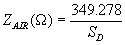
When using this equation, set Sd to the effective area of the box output. If it’s a simple sealed cabinet, then this is just the effective total driver area of all mutually coupled drivers. In a horn loaded cabinet, Sd is the mouth area of the horn.
If the cabinet is vented, then the result may need to be broken into two parts. Since the output of a vented box is at the driver above the box frequency and at the port at box frequency, the driver area changes from the size of the speaker to the size of the vent. One method is to place a resistor at each output. The problem then is that you then ignore mutual coupling between the driver and the vent. Another method is to tie the two outputs together, and run the simulation twice, once with the large impedance and once with the small impedance. And yet another method is to model the mutual coupling between the two (or more) outputs. This requires a few more components, but simulates each output’s effects on the other.
If you wish to model the effects of other cabinets or other outputs of the same cabinet in proximity to that output, then the answer is more complex.
{Model yet to be determined} {Same as mutual coupling}
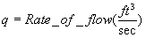
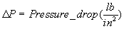
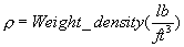
Resistance to Air Flow



Miscellaneous Equations
Velocity of propagation in a transmission line/wave guide:


U = 290 m/sec
Characteristic impedance of a transmission line:
